
The right material alone won’t make a robotics tray work. Material, cavity geometry, and pickup access must function as one system. For custom precision foam trays for robotics assemblies in Silicon Beach, consider material selection early in the design process because it affects part support, repeated handling, and how reliably automation can locate and remove components.
It’s easy to focus first on keeping parts snug. But a pocket that restrains a component too tightly can complicate robotic pickup, while poor locating features can make tray positioning inconsistent. The design needs to balance a secure fit with clear access for the robot and the handling process.
This article explains how material choice, CAD design, fitted inserts, forming, and part orientation shape tray performance. You’ll see how to assess stiffness, static sensitivity, cleaning needs, cavity layout, stack separation, and pickup clearance so the tray supports both the parts and the assembly workflow.
Key Takeaways
- Choose tray material around reuse, static sensitivity, heat, and cleaning needs, not fit alone.
- Coordinate CAD locating features and cavity layout with the automation cell so trays can be positioned consistently.
- Balance pocket support with clearance for the robot’s pickup method and the component’s orientation.
- Account for forming, trimming, stiffness, and stack release when designing trays for automated handling.
- Custom foam packaging and packaging inventory programs can help align protective packaging with production and supply needs.
Foam Packaging Products
Robotics components need packaging that keeps parts separated during staging and movement without slowing assembly. Foam packaging can cushion motors, sensors, housings, and other delicate components, while an organized insert helps operators return each part to its designated position. Stock foam packaging can suit routine cushioning when a standard format fits the part and workflow. Custom foam inserts are a better fit when components have distinct shapes, need separation, or must stay arranged for handling.
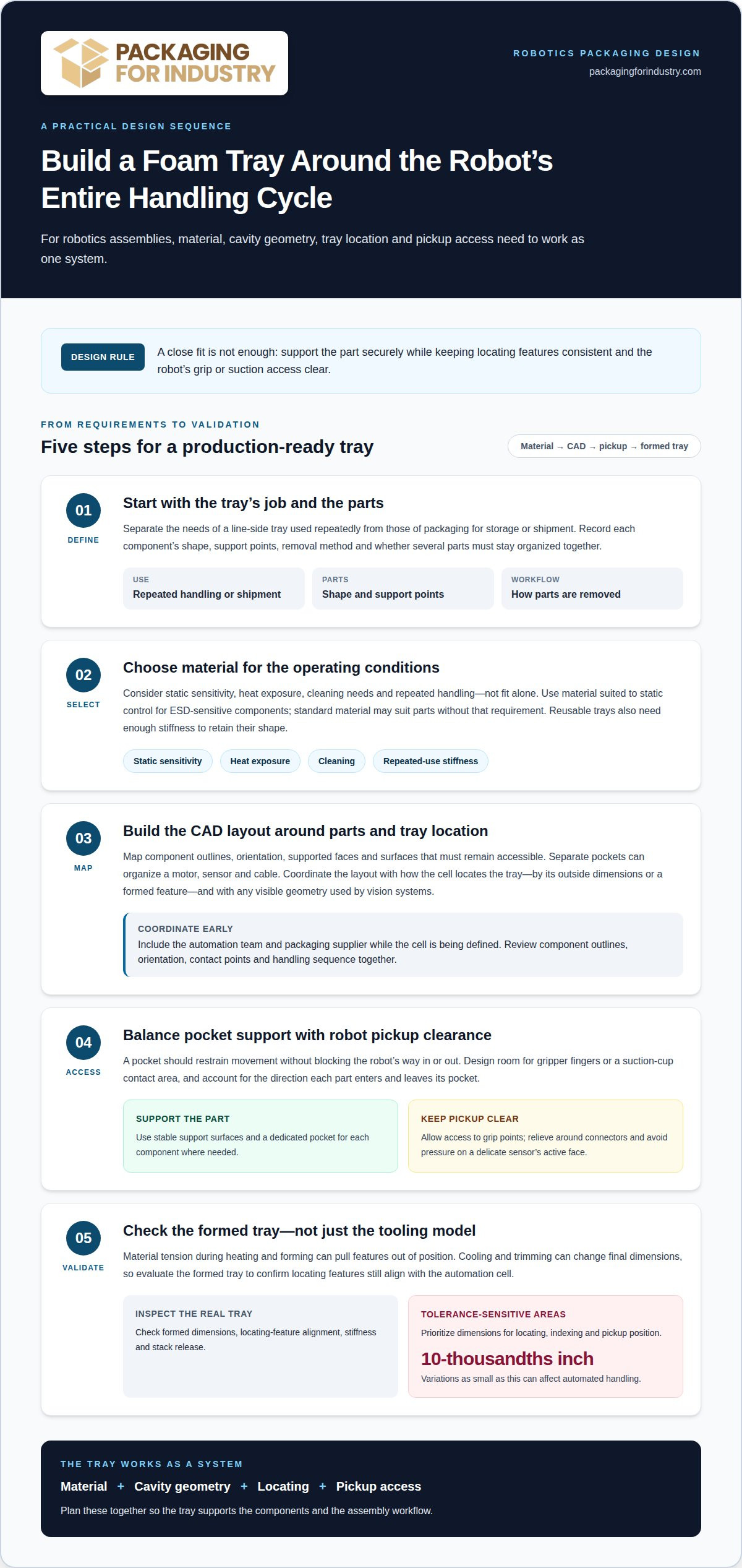
The choice depends on how the tray will be used. A protective insert for storage or shipment has different requirements from a line-side tray used repeatedly in production. Consider the component’s shape, support points, removal method, and whether the insert must hold several parts together. These details guide a custom design that makes parts easier to identify and handle while limiting unnecessary movement inside the package.
Custom packaging design services can align foam inserts with the assembly’s component layout and packaging workflow. They’re useful when stock formats leave excess space, fail to separate parts, or make access awkward. For robotics businesses in the Silicon Beach area, the same packaging planning can support local operations, including those in Huntington Beach. Share the part layout, handling needs, and intended packaging use when requesting a foam packaging quote. That gives the design process practical details to work from and helps shape a fit-for-purpose solution.
Materials for reusable and ESD-sensitive trays
For reusable robotics trays, choose material based on static sensitivity, heat exposure, cleaning, and repeated handling. ESD-sensitive components need packaging suited to static control; standard material may suit parts without that requirement. A line-side tray also needs enough stiffness to retain its shape through repeated use. Account for these requirements before finalizing tooling.
Material tension affects how a tray forms and aligns. During heating and forming, uneven tension can pull features out of position. Cooling and trimming can also change final dimensions, so the formed tray may differ from the original tooling geometry. Evaluate the tray after forming to confirm its locating features still align with the automation cell.
For delicate assemblies, control tolerances most closely on dimensions used for locating, indexing, and pickup. Variations as small as 10-thousandths inch can affect automated handling. Pocket clearance must restrain movement without blocking the robot’s grip or suction access. ESD control and repeatable positioning should be considered together when parts are sensitive.
For robotics equipment shipped within California, choose packaging to suit the route, handling conditions, and destination requirements. Use ESD-sensitive packaging where components require static control, and follow the carrier’s packaging and labeling instructions. The equipment’s fragility and handling path should shape the protective design.
A foam packaging quote can account for material behavior, formed dimensions, alignment needs, and component sensitivity.
CAD-based foam engineering
A CAD layout translates each component’s shape and orientation into a coordinated insert. The model can map separate pockets for a motor, sensor, and cable, keeping parts organized for a defined assembly operation. It should also show which faces need support and which surfaces must remain accessible. This helps engineers design the insert around the actual parts rather than rely on a generic cavity.
Grippers need room to approach, engage, and lift components cleanly. CAD planning can account for finger clearance or a suction-cup contact area, along with the direction each part enters and leaves its pocket. A pocket that fits the component but blocks the gripper can interrupt the operation. Including the pickup path connects part protection with automation needs.
Locating features also matter. The assembly cell may position a tray by its outside dimensions or by a formed feature, while vision systems may depend on visible geometry. Variations as small as 10-thousandths inch can affect automated handling. The CAD design should therefore prioritize dimensions that control locating, indexing, and pickup position, rather than treating every tray dimension as equally critical.
Involve the automation team and packaging supplier while the cell is still being defined. This lets the team coordinate the insert layout with grippers, tray positioning, and tooling before production decisions are fixed. Include component outlines, orientation, contact points, and handling sequence in the design review. For a reusable setup, consider how insert weight and overall dimensions affect operator handling and line-side placement.
Custom-fitted foam inserts
A custom insert can give each robotics component a dedicated pocket, such as separate spaces for a sensor, motor, and cable harness. Pocket shapes should support stable surfaces while leaving edges or grip points accessible. This layout helps operators identify components during manufacturing and return them to consistent positions during production handling.
Design around how parts enter and leave the insert. A molded housing may need relief around a connector, while a delicate sensor needs support that avoids pressure on its active face. Arm tooling also needs a clear approach path. If a gripper cannot reach its contact area, a close-fitting pocket can slow retrieval instead of supporting repeatable handling.
Minimum order quantities for custom foam packaging depend on the design, tooling, material, and production run. A one-off insert and a repeat production order can have different requirements. The requested quantity and intended use help establish a practical production plan without treating every custom design as the same job.
Before production, the insert design should account for the component arrangement, access points, and how parts are replenished. For example, a kitting layout may group components in the order an assembly operator uses them, while a shipping insert may prioritize separation and support. Share these use details when you request a custom foam quote, so the design can reflect the actual handling sequence.
An example involving insertion of a 16-thou wire into a 17-thou medical needle shows the close alignment that robotic assembly can require. For an insert staging parts for comparable work, make each component’s orientation easy to recognize without forcing an operator or gripper to pinch a delicate feature. Consider how the wire is presented for pickup, which surface can be contacted, and whether the needle can remain steady as the assembly step begins. The pocket should hold each part in a predictable position while still allowing removal along a clear path. Keeping delicate ends free from unnecessary contact can help ensure that staging does not obstruct the assembly operation.
Review the layout from the tool’s approach point, not only from above. A pocket may look appropriately close-fitting yet make pickup awkward if a wall blocks the gripper or leaves too little room to withdraw the part. If components are staged for a linked task, consider whether their orientation supports the intended sequence and whether they can be replenished without disturbing nearby parts. Use sample components to check how they settle, how easily they can be grasped, and whether they return to the same position after removal. Adjust pockets to preserve useful support while keeping required contact areas accessible. These checks help translate the assembly task into an insert that supports orderly staging and consistent access.
Forming and die-cutting processes
Thermoformed tray production has two basic processes: a forming station and a cutting station. The forming station shapes material against tooling; the cutting station trims the formed tray to its outline. Separating these functions helps identify whether a fit issue comes from cavity geometry or the tray’s outer edge.
For shaped cavities, mold features should create the pockets rather than relying on trim features. A molded pocket for an electronics housing can control its position while preserving the flange for cutting. Tooling should account for the cavity’s function and the surfaces automation uses to locate the tray.
Stack release also affects design. Nesting depth, separation features, and material stiffness influence how trays separate during automated handling. For example, a deep pocket may organize a component but complicate release if adjacent trays bind. Consider these conditions alongside the formed surface and component access.
CNC routing and waterjet cutting use different methods. CNC routing removes material with a rotating cutter and can form pockets at controlled depths. Waterjet cutting uses a high-pressure water stream to cut a profile through sheet material. For robotics assemblies, compare cavity depth, profile, material, and required edge condition before selecting a process.
Choose a process based on the tray’s actual job. A flat insert with defined cutouts may call for a different approach than a tray with formed walls and shaped cavities. Align tooling, locating features, and cut paths with the automation cell so the finished tray supports the required handling sequence.
Part orientation and pickup access
Tray orientation must match how equipment establishes position. A conveyor may locate a tray by its outside dimensions, while an indexing station may use a formed feature. Visual features or symbols molded or machined into the tray can help a robotic system locate and orient it consistently.
Pockets should limit component movement without blocking removal. A suction cup needs a clear contact surface; a gripper needs space to close around its target. For example, a plastic housing with a side connector may need an open access area so the robot can lift it without catching the connector.
Orientation also affects inspection. Cavity geometry and material appearance can influence whether a vision system locates or inspects a component. Positioning a sensor with its inspection face visible can support the camera’s task, while a pocket that hides that face may interfere with automated checks.
Plan tray stacking alongside pickup. Some automation trays use 180-degree rotational stacking, allowing empty trays to nest while keeping the tray above from loading the parts. Separation features and material stiffness influence release from the stack. Coordinate those details with the picker head and handling equipment, then assess the finished tray’s access points in the intended orientation. Parts may be placed in or removed using suction cups, grippers, or gravity, so the pocket must suit the selected method and the component’s shape.
Tighten thermoformed tray tolerances on dimensions that directly affect locating, indexing, or pickup, rather than across the entire tray. Robotic pockets should control movement while still allowing removal. Manufacturers often develop trays alongside automation companies, picker heads, and pick-and-place equipment.
Industries Served
Robotics manufacturers in Silicon Beach need packaging suited to components moving through production, inspection, and shipping. Custom precision foam trays for robotics assemblies in Silicon Beach can support organized handling when each component needs a defined place. Custom packaging design connects the packaging layout with the product and operation instead of relying on a general-purpose format.
Electronics businesses handle assemblies with specific protection and handling needs. Medical device and aerospace manufacturers also move components through storage and distribution. Packaging plans can account for how products are arranged and packed; aerospace packaging solutions serve manufacturers handling components across these workflows.
Food and beverage companies, construction suppliers, distributors, fulfillment centers, and warehouse operations also manage packaging requirements tied to product movement. Foam packaging can cushion or separate components inside a package, while stretch film can secure unit loads during storage and transport. The right combination depends on the goods and how they move through the facility.
For buyers sourcing custom precision foam trays for robotics assemblies in Silicon Beach, the design is only part of the purchasing decision. Consistent supply matters, too. Vendor Managed Inventory for packaging can help coordinate replenishment with recurring use. Across robotics, manufacturing, and distribution, consider product protection, packing work, and the route through the operation.
Benefits of Custom Foam Trays
A tray designed around component shapes can keep parts separated and limit movement during handling and transit. For example, individual pockets can prevent a sensor from contacting a motor housing in the same package. Better organization can also make packing and line-side retrieval more consistent, helping teams reduce avoidable handling errors and product damage.
Custom sizing can help control packaging use. A tray that fits the components and outer package can avoid excess interior space and reduce reliance on extra loose cushioning. The practical benefit depends on the product mix, shipping method, and handling. Reviewing the full package, not just the insert, helps identify opportunities to lower packaging costs.
Repeatable pocket layouts support predictable packing. Operators can see where each component belongs, while a defined arrangement can simplify staging and replenishment. For robotics assemblies with several related parts, a consistent tray layout can make missing or misplaced components easier to spot before the package moves to the next operation.
Supply reliability also depends on a design that can be produced consistently and managed alongside production demand. Aligning the insert specification with packaging inventory planning can help avoid last-minute substitutions that disrupt packing routines. A custom foam design is most useful when it addresses a fit, protection, or workflow issue that standard packaging doesn’t solve.
Packaging For Industry (PFI): Foam Packaging
Packaging For Industry (PFI) helps robotics teams address component fit, handling, and packaging supply through foam packaging and custom packaging design. For a tray used in production or shipping, the design can account for part layout, orientation, and access. Sharing component drawings, handling needs, and intended use gives the design process practical project details.
Custom packaging design is useful when stock cushioning doesn’t suit the assembly or workflow. A fitted insert can organize components and support a consistent packing routine. PFI’s custom packaging design services connect the packaging layout with the products being handled, helping manufacturers develop a solution suited to their operation.
Stretch film serves a different role. It can secure packaged robotics equipment or other unit loads during movement and storage, complementing protective foam inside the package. The right combination depends on what needs cushioning, what needs load containment, and how the shipment moves through the warehouse.
Packaging VMI can help businesses coordinate replenishment with operational use. It’s relevant when managing foam and other packaging supplies creates purchasing or inventory pressure. A discussion can cover the packaging items in use, demand patterns, and how replenishment should fit the workflow.
Contact Packaging For Industry (PFI) to discuss foam packaging, tray design, stretch film, or packaging VMI for your robotics operation.
Move Your Tray Project Forward
The next step is to connect the tray design with the production plan. For robotics teams considering custom precision foam trays for robotics assemblies in Silicon Beach, discuss how parts move from storage to assembly, inspection, and shipment. That operational context helps turn design choices into a packaging approach that supports the work rather than adding another handling constraint.
Packaging For Industry (PFI) offers foam packaging, stretch film, and Vendor Managed Inventory for packaging. These offerings can support product protection and packaging supply planning as part of a broader project. A quote discussion can focus on your assembly requirements, intended tray use, and packaging workflow, then identify relevant next steps.
Starting with the application keeps the conversation practical. It helps design and purchasing teams align packaging decisions with production needs and supply planning, while keeping attention on fit, access, and consistent handling.
A well-planned packaging project gives your robotics team a clear path from design decisions to dependable day-to-day handling.
Frequently Asked Questions
Where Does Material Selection Fit?
Choose the material early in tray design, before tooling and the automation layout are finalized. This lets the design account for component sensitivity, intended reuse, cleaning, and production conditions before those decisions become costly to change. Identify static-sensitive electronics and any surfaces that must remain protected, then match the material to the tray’s actual role in storage, line-side use, or shipping.
Which foam materials can protect robotics assemblies during storage and shipping?
Options include polyethylene foam, polyurethane foam, and anti-static or ESD foam. Packaging For Industry also offers EPE, EPP, EPS, and cross-linked XLPE foam. The right choice depends on the part and packaging task: static-sensitive electronics need ESD-conscious cushioning, while assemblies with different shapes may need tailored inserts or foam end caps. Consider whether the package protects one component or organizes several parts together.
How should I specify custom foam inserts for robotic components?
Provide component drawings or samples, the quantity and arrangement of parts per package, and details about how the package will be used. Identify delicate surfaces, connectors, and components that must stay separate. Specify whether the insert is for storage, internal production movement, or outbound shipping. For changing product configurations, indicate which parts vary so the layout can account for those differences.
custom precision foam tray manufacturers near Silicon Beach Los Angeles
Custom packaging design services can align foam inserts with robotics components and workflows in the Silicon Beach area, including Huntington Beach.